
English
Views: 0 Author: Site Editor Publish Time: 2021-08-18 Origin: Site


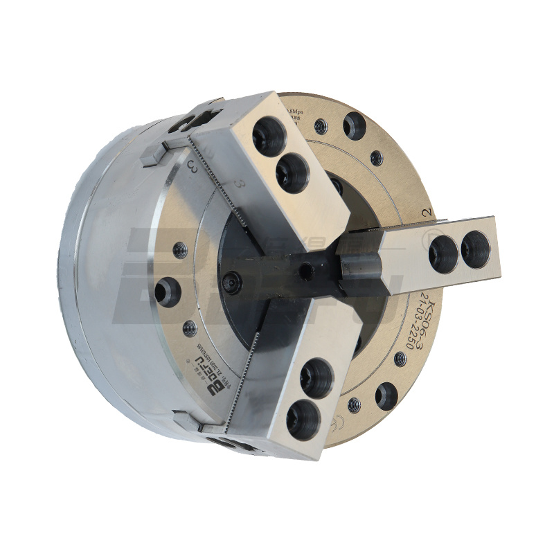
Manual three-jaw chuck structure:
The three-claw chuck is composed of a claw plate body, a small bevel gear, a large bevel gear (the other end is a plane thread) and three claws. The three claws have the same threads as the plane threads to match them. The three claws are evenly distributed at 120 degrees in the guide groove in the claw plate body. The tapered hole of the claw plate body cooperates with the outer conical surface of the front end of the lathe spindle to play a centering role. The torque is transmitted through the key, and then the chuck body is locked on the spindle with a nut.
When one of the small bevel gears is rotated, the large bevel gear is driven to rotate, and the plane thread on it drives the three claws to move toward the center or outward at the same time, thereby achieving automatic centering. The centering accuracy is not high, about 0.05~0.15mm.
The three claws are divided into positive claws and reverse claws. In some chucks, the claws can be reversed to form reverse claws. When the reverse claws are replaced, larger diameter workpieces can be installed. When the diameter is small, the workpiece is clamped between three long claws (a below). The three claws can be extended into the inner hole of the workpiece and the radial tension of the long claws can be used to clamp the disc, sleeve, and ring-shaped parts. When the diameter of the workpiece is large and it is inconvenient to clamp with the parallel claws, the three parallel claws can be replaced with anti-claws for clamping. When the length of the workpiece is greater than 4 times the diameter, the right end of the workpiece should be supported by a tailstock thimble.

