
English
Views: 0 Author: Site Editor Publish Time: 2021-09-29 Origin: Site


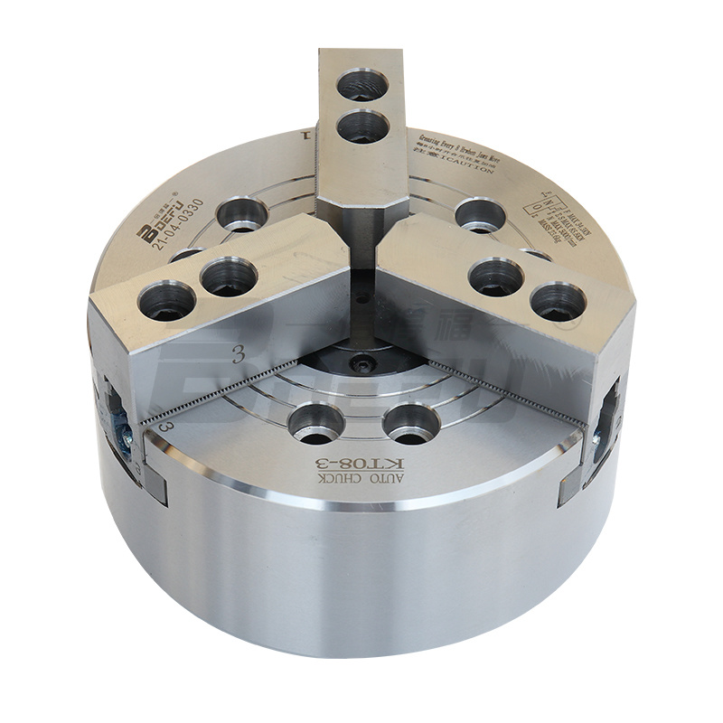
Background technology: The pneumatic chuck has a body accuracy of 0.010mm and a high speed of up to 5000rpm. It is a high-end and high-performance pneumatic chuck with hollow through holes that can work with an automatic feeding system to improve production efficiency. Currently, pneumatic chucks have been widely used in various applications such as workpiece clamping systems for CNC lathes or special processing machines, automation of traditional lathe modifications, grinding machines, or fourth-axis indexing chucks installed in CNC machining centers.
However, the traditional pneumatic chuck must rely on manpower when locking the workpiece. Manually tightening the workpiece with a chuck wrench is time-consuming and laborious, which seriously affects production efficiency. During the rotation of the pneumatic chuck, it is easy to cause its own displacement due to the rotation speed, resulting in a short service life of the equipment. Therefore, those skilled in the art provide a rotatable hollow three-jaw pneumatic chuck to solve the problems raised in the above background art.
Technical implementation elements: The purpose is to provide a rotatable hollow three-jaw pneumatic chuck to solve the problems raised in the above background technology.
In order to achieve the above purpose, the present utility model provides the following technical solutions:
A rotatable hollow three-claw pneumatic chuck includes a bearing seat, claws, a pulley and a spindle. The claws are fixedly installed inside the main shaft, and the pulley is installed on the rear surface of the main shaft. The outer surface of the claws is sleeved with a locking device. The bottom of the spindle is fixedly installed with a bearing seat. A positioning assembly is fixedly installed at the connection between the inside of the bearing seat and the spindle.
As a new and further solution: the positioning assembly includes a first spacer, a first bearing, a second spacer, a second bearing and a circlip. The first bearing is fixedly installed at the connection between the inside of the bearing seat and the main shaft. The first spacer is fixedly installed at the middle of one side surface of the first bearing and the pulley.
As a new and further solution: the number of the first bearings is four, the number of the second bearings is two, the outer diameter of the first bearing is larger than the outer diameter of the second bearing, the inner diameter of the first bearing is equal to the inner diameter of the second bearing, and the number of the first spacer sleeve, the second spacer sleeve and the circlip is two.
As a new and further solution: the locking device includes a compression spring, a connecting ear, a roller, a cylinder, a cylinder rod, a baffle, a thrust bearing and a wedge sleeve. A roller is fixedly installed on the top of the claw, and compression springs are fixedly installed on both sides of the roller. The compression spring penetrates the interior of the main shaft and is connected to the upper surface of the claw. , the outer surface of the main shaft is sleeved with a wedge-shaped sleeve, the outer surface of the wedge-shaped sleeve is fixedly installed with a connecting lug, and the rear surface of the wedge-shaped sleeve is equipped with a baffle. A thrust bearing is installed between the wedge-shaped sleeve and the baffle. The inside of the connecting lug is connected to a cylinder rod through a nut, and the cylinder rod penetrates the inside of the cylinder.
As a new and further solution: the number of the rollers is three, the adjacent compression springs are installed symmetrically with the center of the rollers as the center, and the connecting ears are symmetrically arranged on both sides with the center of the wedge sleeve as the center.
As a new and further solution: the number of the cylinders is two, and the cylinders are symmetrically installed on both sides of the bearing seat. The number of the baffles and thrust bearings are both two. The baffles are fixedly installed on the rear surface of the wedge sleeve through bolts.
Compared with existing technology, the new beneficial effects are:
1. The newly installed positioning component uses the inside of the bearing seat to separate the pulleys through the first spacer. At the same time, the four first bearings installed inside the bearing seat and the second spacer installed between the first bearing and the second bearing can ensure that when the pulley drives the spindle to rotate, the spindle rotates according to its own axis without displacement in any direction. The overall design effectively improves the service life of the equipment, prevents vibrations caused by the workpiece during processing, and improves the product qualification rate.
2. The new locking device uses two cylinders to move synchronously. The cylinder drives the cylinder rod to extend and drive the connecting lug forward. The force is transmitted to the wedge sleeve through the thrust bearing, causing the wedge sleeve to move forward. The wedge sleeve presses the three rollers to rotate at the same time and moves the three claws inward to the center synchronously. The workpiece is tightened to achieve the purpose of tightening the workpiece, ensuring that the air source is always in a pressure-maintaining state during the tightening process, ensuring that the workpiece is always tightened by high pressure. The wedge-shaped structure is used to be fast and efficient, with stable operation and low wear, which improves production efficiency, reduces manual labor intensity, and saves production costs.

