
English
Views: 0 Author: Site Editor Publish Time: 2021-09-10 Origin: Site


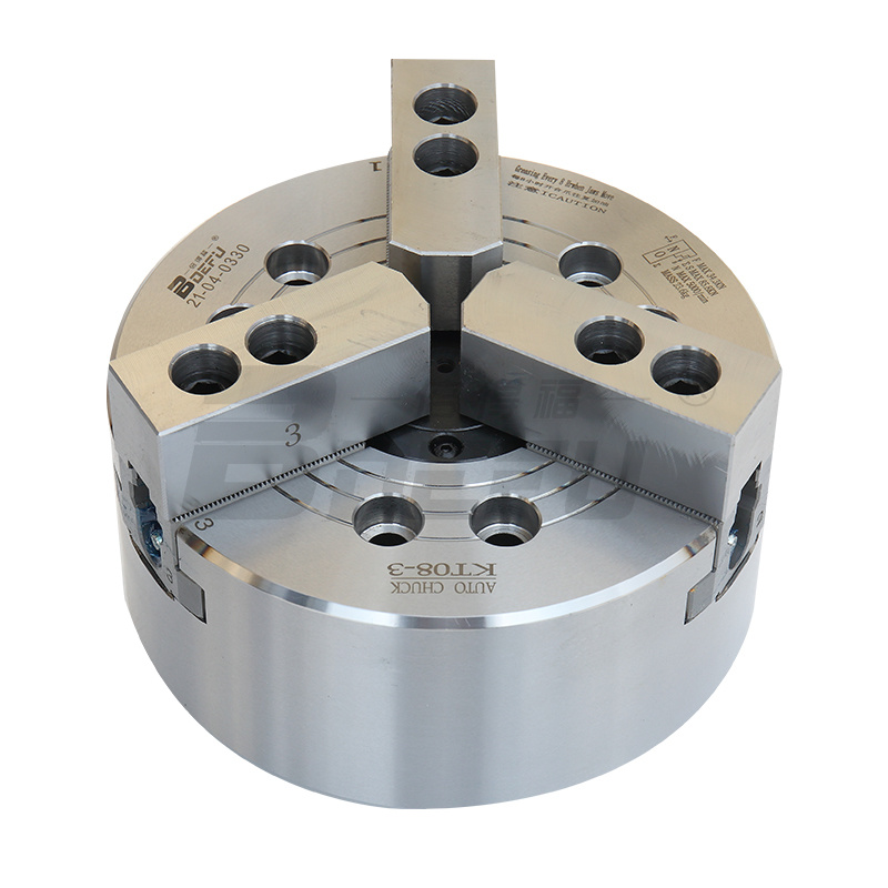
1. Install the chuck onto the tie rod. Remove the soft claws and dust cover of the chuck, lock the threads with screws No. 1, 2, and 3. Place the sleeve wrench on the center hole of the chuck. Lock the tie rod nut into the tie rod. Depending on whether the oil pressure is at 4-5kgf/cm2, move the tie rod back and forth 2-3 times and lock the nut smoothly.
2. When the tie rod nut is locked on the tie rod, if it is not locked smoothly, you should recheck whether the center of the thread is tilted, etc. If it is forced to lock, it will cause accuracy errors and damage to the thread.
3. Install the chuck on the spindle. Turn the sleeve wrench until it is securely coupled to the end face of the spindle. Lock the screws in the following order
Note: Please tighten the chuck connecting screw according to the set torque. If the locking torque is insufficient or too strong, an accident may occur.
The above attached screws are for usage principles. If there are special circumstances, please use 12.9 or above (M22 or above 10.9) and have sufficient length.
Use a sleeve wrench to adjust the position of the pull plate and maintain a gap of 0.5mm-1mm between the pull plate and the body. At this time, the base claw is at the beginning.
Install the dust cover and check the deflection of the chuck. Make the outer edge and end face of the chuck deflect within 0.02mm.

