
English
Views: 0 Author: Site Editor Publish Time: 2021-10-21 Origin: Site


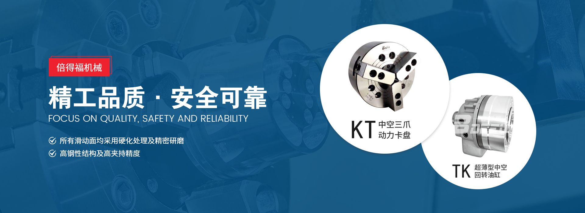
Hydraulic power chucks are widely used in CNC machine tools! Today I will mainly introduce the hydraulic chuck structure!
1. Wedge hydraulic power chuck
The wedge structure is a commonly used structural form of hydraulic power chucks. It converts the axial movement of the chuck piston into the radial movement of the jaws through the wedge groove mechanism (the most common type of hydraulic chuck)
2. Helical tooth slider hydraulic power chuck
The chuck of this structure first uses a wedge groove mechanism to convert the axial movement of the chuck piston into the movement of three slide blocks in its chute. The tops of these three slide blocks are equipped with helical teeth, which form a bevel meshing relationship with the teeth at the bottom of the claw. The movement of the slide block drives the claw to move radially. The workpiece is clamped by the movement, and the clamping force is large, the clamping accuracy is high, and the mechanism wear is small; because the moving direction of the slider in the chute of the chuck is basically perpendicular to the direction of the centrifugal force of the claw, the clamping force of the chuck is very little affected by the centrifugal force, and the chuck has good high-speed performance.
3. Wedge-lever power chuck
The piston drives the wedge gear block through a wedge mechanism, and then drives the claw through a straight lever. This structure has a small claw mass, and the centrifugal force of the wedge tooth block compensates for the centrifugal force of the claw, reducing the loss of clamping force and helping to increase the rotation speed. The fulcrum of the lever is designed as a spherical support to withstand higher pressure! (There are no internal pictures yet)
4. Pull-in chuck
This chuck is generally used to clamp slender shafts. It relies on the axial movement of the jacket and the matching of the cone surface to change the diameter of the jacket.

