
English
Views: 0 Author: Site Editor Publish Time: 2021-10-08 Origin: Site


How to transform an ordinary chuck into a 'flexible clamp'
When using CNC lathes to turn bearing rollers, there are certain problems with the machine tool's own fixture: it is only suitable for turning bars with relatively thin dimensions; when the bars are thicker (larger than Φ45mm), the clamping force is insufficient, causing problems such as damage to the tools and fixtures. For this reason, after actual analysis, it was decided to transform the self-contained clamp into an elastic clamp.
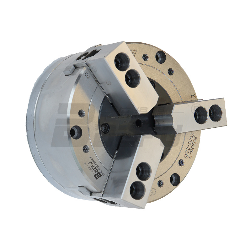
Lathes mainly machine bearing rollers. The original design of the lathe comes with an ordinary wedge-type hollow hydraulic power three-jaw chuck, as shown below.
▲ Hydraulic power three-jaw chuck
This kind of chuck uses a hollow pull rod to push the connection plate to move upward under the action of oil pressure. The slider moves accordingly, transmitting the force to the clamping jaws, and the squeeze jaws move along the slideway to clamp the workpiece; when the hollow pull rod pushes the connection plate to move downward under the action of oil pressure on the other side, it drives the clamping jaws to move away from the center of the circle, that is, the clamping jaws are opened.
▲Hydraulic clamping mechanism
In order to reduce the material head and improve material utilization, the equipment is designed with a bar length of 3m. The bar material relies on the support of the material rack and guide sleeve, enters the rotary cylinder, and is clamped by the clamping jaw after passing through the hollow tie rod. The gap between the bar and the guide sleeve is 2~3mm, and there is a certain bending phenomenon in the bar. Therefore, when the speed reaches the rated speed, the clamping jaw loses more clamping force due to the centrifugal force of the bar. As the diameter of the workpiece increases, the centrifugal force of the bar increases, and the cutting force on the workpiece also increases. The clamping force of the clamping jaws will be insufficient, and the bar often rotates and moves backward, resulting in roller waste.
▲ The material rack and guide sleeve support the bar mechanism
In order to solve the problem of insufficient clamping force, try to increase the oil pressure to the ultimate oil pressure of 2.8~3.0MPa to increase the clamping force of the chuck and meet the work needs. However, at the same time, phenomena such as clamping of the bar surface, deformation of the power chuck gland, breakage of bolts and spare caps, damage to the material pipe threads, instant tool collision, and causing the turning tool to jump. When processing rollers above Φ45mm, the work needs can only be met by reducing the speed or shortening the length of the rod (from 3m to 2m), which greatly reduces production efficiency or material utilization.
In order to fully improve the utilization rate of this equipment, while reducing the equipment failure rate and expanding its roller processing range (the diameter of machined rollers is increased to within Φ64mm), the lathe's own fixture has been improved.
▲ Elastic clamp structure
The improved clamp cancels the original ordinary hydraulic three-jaw chuck and redesigns and manufactures an elastic clamp. The newly designed clamp mainly consists of spring sleeve chuck, clamping ring, clamping block, clamp body, transition plate, material tube, safety shield and other components. The installation steps are shown below.
▲Elastic clamp installation steps
The clamp body is connected to the spindle through a transition plate. The spring sleeve collet is installed in the clamp body and connected with the material pipe through threads. The clamping ring is installed on the spring collet. The spring sleeve collet is positioned through the clamping ring so that the clamping block can be finely adjusted to position and clamp the outer circle of the bar. After the fine turning is completed, remove the clamping ring.
The inner diameter size of the clamping block of the elastic clamp should be the same as the size of the bar after finishing turning to ensure that the inner arc surface of the clamping block is in full contact with the outer arc surface of the bar, increase the clamping force on the bar, and prevent the bar from rotating and moving backwards. The outer diameter of the clamping block is a standard size, and the remaining components are designed as universal workpieces. When processing rollers with different diameters, you only need to replace different types of clamping blocks to realize the clamping processing of different products. Replacing the clamping block is quick and easy.
1. High centering accuracy, fast and convenient workpiece clamping, and stable workpiece clamping;
2. After changing to elastic clamping, the corresponding clamping block can be made according to the feeding range of the product. The design is simple and easy to make. When changing products, only the clamping block can be replaced to complete the replacement of the clamp;
3. After changing to elastic clamping, when processing large-size rollers, there will be no chipping, bar rotation or displacement, which completely solves the problems of high scrap rate, unstable product quality, and frequent tool damage when clamping workpieces with three-jaw chucks;
4. After changing to elastic clamping, the processing range of the equipment has been increased from the original rollers with a diameter of less than Φ45mm to a roller with a diameter of less than Φ64mm, and the equipment utilization rate has been significantly improved;
5. After changing to elastic clamping, the processing efficiency doubled. For example, when processing small spherical rollers before the transformation, due to the large curvature of the spherical surface, the amount of cutting and cutting force increased when processing chamfers and spherical curvatures. The original three-jaw chuck had insufficient clamping force, and the bar material could not be clamped tightly, which easily caused vibration marks at the chamfers. In order to ensure product quality, it is necessary to reduce the cutting force through two feeds to eliminate the vibration marks generated in the chamfer;
6. Due to the increased clamping force of the elastic clamp, the length of the bar head is also greatly shortened. Compared with the original, the length of each bar head is shortened by 50~60mm, effectively saving raw materials;
7. Since the elastic clamp increases the contact area with the workpiece, the unit pressure between the clamp and the workpiece is reduced without reducing the clamping force, that is, the hydraulic pressure and tooling damage are reduced.

